Milling is one type of conventional machining process primarily for generating flat or stepped surfaces. In peripheral milling, cutting velocity is imparted by rotating the milling cutter about a fixed horizontal axis; whereas, the feed rate is imparted by moving the workpiece (basically worktable) against the rotating milling cutter. Since both cutting velocity and feed rate are vector quantities, so based on their mutual directions, peripheral milling can be classified into two groups—up milling and down milling. Each of them has specific advantages and disadvantages, as illustrated below. Various similarities and differences between up milling and down milling are given in table format in the following sections.
- Up milling or Conventional milling—when feed direction is opposite to the cutter rotation at the point of engagement. Here uncut chip thickness increases with cutter rotation.
- Down milling or Climb milling—when feed direction is along the direction of cutter rotation at the point of disengagement. Here uncut chip thickness decreases with cutter rotation.
Similarities between up milling and down milling
- Irrespective of up or down milling mode, three process parameters (speed, feed and depth of cut) must be provided for machining.
- In case of full immersion end-milling operation (slot cutting), both up-milling and down-milling occur one after another in every rotation for each tooth.
- Same milling cutter can be applied for both the cases; however, the orientation may be different.
- Overall volume of the workpiece material removed in up milling side must be same with the volume of the workpiece material removed in down milling side for similar conditions.
- In both the cases, the maximum chip load is proportional to the given feed per tooth.
Differences between up milling and down milling
| Up Milling | Down Milling |
|---|---|
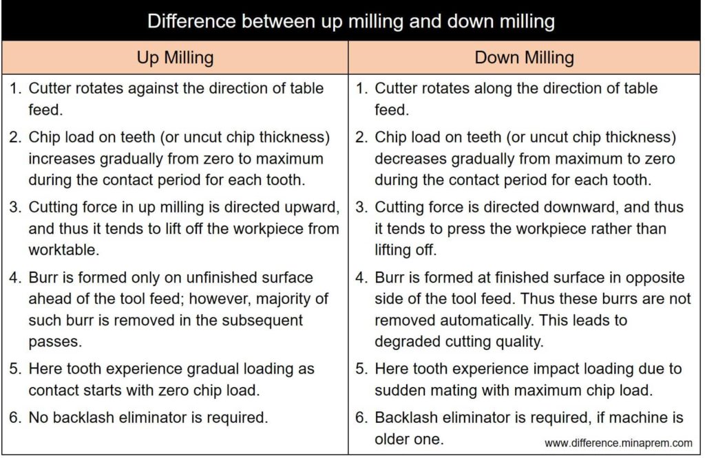
| In up milling, cutter rotates against the direction of table feed. | In down milling, cutter rotates along the direction of table feed. |
| Chip load on teeth (or uncut chip thickness) increases gradually from zero at the point of engagement to maximum at the point of disengagement. | Chip load on teeth (or uncut chip thickness) decreases gradually from maximum at the point of engagement to zero at disengagement. |
| Here tooth experience gradual loading as contact starts with zero chip load. | Here tooth experience impact loading as tooth engages suddenly with maximum chip load. |
| With horizontal axis milling machine, cutting force in up milling mode is directed upward, and thus it tends to lift off the workpiece from the worktable. Accordingly, rigid and expensive fixture is required for firmly mounting the workpiece. | In down milling mode, the cutting force is directed downward, and thus it tends to press the workpiece rather than lift off. So cheaper fixture can be employed. |
| Thin workpiece samples, if machined using up milling mode, may get distorted due to upward cutting force. | Chances of distortion of thin workpiece samples are less with down milling mode if proper support in bottom is provided. |
| Due to gradual buildup of chip load in up milling, heat generation is also high. So there exists a tendency of chip welding with the teeth. | Tendency of chip welding is less in down milling but chip re-deposition on finished surface occurs frequently that may degrade quality of finished surface. |
| Burr is formed only on unfinished surface ahead of the tool feed; however, majority of such burr is removed in the subsequent passes. | Burr is formed at finished surface in opposite side of the tool feed. Thus these burrs are not removed automatically. This leads to degraded cutting quality. |
| At the beginning of engagement, teeth rub with lay or feed marks on the machined surface. This improves surface finish. | No such rubbing action takes place, and thus lay marks remains intact on the machined surface. |
| Besides improving surface finish, rubbing during engagement may result in undesirable work hardening owing to significant heat generation. | Chance of work hardening is minimal with down milling. |
| In up milling mode, no chipping action occurs on teeth of the cutting tool due to gradual contact. Accordingly, tool wear rate is relatively low. | Due to impact loading at engagement, chipping occurs and it may cause notch wear. Thus tool wear rate is high. There also exists a chance of catastrophic failure of the teeth. |
| No backlash eliminator is required. | Backlash eliminator is required, especially if the milling machine is an older one. |
| If the workpiece or cutter material is brittle (such as ceramic), up milling is always preferred. | Down milling is not a good choice if the workpiece material is brittle. |

References
- A Textbook of Manufacturing Technology: Manufacturing Processes by R. K. Rajput (Laxmi Publications Private Limited).
- Elements of Manufacturing Processes by B. S. N. Parashar and R. K. Mittal (PHI Learning Private Limited).
- Saha et al. (2020); An analytical approach to assess the variation of lubricant supply to the cutting tool during MQL assisted high speed micromilling; Journal of Materials Processing Technology. https://doi.org/10.1016/j.jmatprotec.2020.116783
- Saha et al. (2020); An investigation on the top burr formation during Minimum Quantity Lubrication (MQL) assisted micromilling of copper; Materials Today: Proceedings; https://doi.org/10.1016/j.matpr.2020.02.379